

Introduction
As of 2017, ASME Sec. V Art. 4 specifies the use of contoured wedges for examination performed on curved surfaces with diameters less than 14 in. (350 mm). The language regarding contouring changed from “may” to “shall" in 2017, and is now a requirement rather than a suggestion. However, the way paragraph T-432.2 is written can be a little confusing.
Note: Skip to the end if you just want the fancy table!
Do I Need a Contoured Wedge?
The first sentence in T-432.2 uses the term “shall” regarding contouring, but this isn’t always the case. If the pipe diameter is sufficiently large compared the wedge geometry, a flat wedge may suffice.
Part (a) of T-432.2 states:
(a) Search units shall be contoured as required by the following equation:
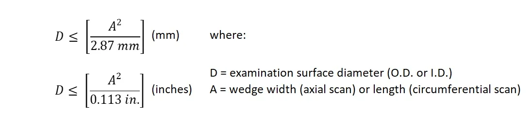
How those equations are supposed to be used isn't well explained. It's in there, it's just that it's implied rather than stated outright. The equation really just tells you the minimum pipe size on which a flat wedge is allowable. A more user-friendly version might look like this (in metric, because it's the friendliest):

How About an Example?
Okee dokee. You are about to inspect a 6 in. nominal (6-5/8 in. OD, or 168.3 mm) circumferential butt weld. To do this, you will be scanning in the axial direction using an Olympus SA10-N55S wedge. Since you are scanning axially, we set A in the equation above equal to the wedge width of 23 mm.
Note: This assumes the footprint is the full wedge width, without chamfered outside edges. If the wedge is chamfered, use the actual footprint width.
Now, plug D (168.3 mm) and A (23 mm) into the left and right sides of the equation:
left side: 168.3
right side: (23)^2 / 2.87 = 184.3
The left-hand side is less than the right-hand side, so we need to contour our wedge.
How Much Do I Contour?
This part is even easier. Simply refer to the tables in T-432.2 (b). Here's one below for examination from the OD:

On a 6-5/8 in. OD pipe, we land on the 2nd row in the table. There can be only an increase in contour diameter, so the wedge must be contoured greater than or equal to the pipe OD (6-5/8 in.), but less than 8-5/8 in.
Note: A contoured wedge might be suitable for a smaller pipe than what it matches but can never be used on a larger pipe because of the potential gap at the sound entry point.
Can You Just Make Me a Table?
Here you go, just follow these two steps:
1) Find your wedge dimension (some common Olympus wedges are already waiting for you). If you’re scanning a circumferential weld, start on the left side of the table and find your wedge width. If you’re scanning circumferentially, look on the right side and find your wedge length. If your wedge is chamfered, be sure to use the footprint dimension (flat part on the bottom, not counting the chamfers).
2) Find your pipe diameter at the top, then follow it down and match up with your wedge. If you land in the grey, you need to contour. If you land in the white, you can use the wedge flat.

Conclusion
This is my interpretation of T-432.2. I hope you find it useful. I find pictorial things like this much more helpful than paragraphs upon paragraphs of obtuse and legal-sounding mumbo jumbo. Just imagine how many trees we saved!
Disclaimer
Follow your procedure. If this isn’t in your procedure, consult your Level 3.
I jammed my logo in the corner so it will follow you around if you print this page. You could white it out, but that would just be mean.